USB-I2C変換ボード(DIO-8/4RE-UBC)を使用して、パソコンからアナログ値を測定する(Python)
python-ft4222がインストールされてない場合は、インストールします。
$ pip install ft4222
プログラムの作成
「test_aio320ra_ft4222.py」というファイル名で以下のファイルを保存します。
(または test_aio320ra_ft4222.py からダウンロードします)
import ft4222
import ft4222.I2CMaster

class PCA9554:

    class Register:
        InputPort = 0
        OutputPort = 1
        PolarityInversion = 2
        Configuration = 3

    def __init__(self, address, i2c):
        self.address = address
        self.i2c = i2c

    def set_direction(self, value):
        self.i2c.i2cMaster_Write(self.address, bytes([self.Register.Configuration , value]))

    def write(self, value):
        self.i2c.i2cMaster_Write(self.address, bytes([self.Register.OutputPort, value]))

class ADS1115:

    class Register:
        Conversion = 0
        Config = 1
        LoThresh = 2
        HiThresh = 3

    class SingleShotCoversion:
        NoEffect = 0
        Begin = 1

    class Mux:
        Ain0_Ain1 = 0
        Ain0_Ain3 = 1
        Ain1_Ain3 = 2
        Ain2_Ain3 = 3
        Ain0_Gnd = 4
        Ain1_Gnd = 5
        Ain2_Gnd = 6
        Ain3_Gnd = 7

    class PGA:
        PGA_6_144V = 0
        PGA_4_096V = 1
        PGA_2_048V = 2
        PGA_1_024V = 3
        PGA_0_512V = 4
        PGA_0_256V = 5

    class Mode:
        Continuous = 0
        PowerDownSingleShot = 1

    class DataRate:
        DR_8SPS = 0
        DR_16SPS = 1
        DR_32SPS = 2
        DR_64SPS = 3
        DR_128SPS = 4 # Default
        DR_250SPS = 5
        DR_475SPS = 6
        DR_860SPS = 7

    class ComparatorQueue:
        Disable = 0x03

    def __init__(self, address, i2c):
        self.address = address
        self.i2c = i2c

    def analog_read(self, mux, data_rate, pga):
        self.i2c.i2cMaster_Write(self.address, bytes([self.Register.Config, self.SingleShotCoversion.Begin << 7 | mux << 4 | pga << 1 | self.Mode.PowerDownSingleShot, data_rate << 5 | self.ComparatorQueue.Disable]))

        data = bytes([0])
        while data[0] & 0x80 == 0:
            data = self.i2c.i2cMaster_Read(self.address, 1)

        self.i2c.i2cMaster_WriteEx(self.address, ft4222.I2CMaster.Flag.START, bytes([self.Register.Conversion]))
        data = self.i2c.i2cMaster_ReadEx(self.address, ft4222.I2CMaster.Flag.REPEATED_START | ft4222.I2CMaster.Flag.STOP, 2)
        word_data = data[0] * 0x100 + data[1]
        if word_data >= 0x8000:
            word_data -= 0x10000
        return word_data

class AIO_32_0RA_IRC:

    class PGA:
        PGA_10_0352V = ADS1115.PGA.PGA_2_048V
        PGA_5_0176V = ADS1115.PGA.PGA_1_024V
        PGA_2_5088V = ADS1115.PGA.PGA_0_512V
        PGA_1_2544V = ADS1115.PGA.PGA_0_256V

    class DataRate:
        DR_8SPS = ADS1115.DataRate.DR_8SPS
        DR_16SPS = ADS1115.DataRate.DR_16SPS
        DR_32SPS = ADS1115.DataRate.DR_32SPS
        DR_64SPS = ADS1115.DataRate.DR_64SPS
        DR_128SPS = ADS1115.DataRate.DR_128SPS
        DR_250SPS = ADS1115.DataRate.DR_250SPS
        DR_475SPS = ADS1115.DataRate.DR_475SPS
        DR_860SPS = ADS1115.DataRate.DR_860SPS

    multiplexerSettings = 0xff

    def __init__(self, ads1115_address, pca9554_address, i2c):
        self.ads1115 = ADS1115(ads1115_address, i2c)
        self.multiplexer = PCA9554(pca9554_address, i2c)
        self.multiplexerSettings = 0xff
        self.multiplexer.write(self.multiplexerSettings)
        self.multiplexer.set_direction(0)

    def analog_read(self, channel, data_rate, pga):
        if (channel < 16):
            extMux = (self.multiplexerSettings & 0xf0) | channel
            adcMux = ADS1115.Mux.Ain0_Gnd
        elif (channel < 32):
            extMux = (self.multiplexerSettings & 0x0f) | (channel & 0x0f) << 4
            adcMux = ADS1115.Mux.Ain1_Gnd
        elif (channel < 48):
            extMux = (self.multiplexerSettings & 0xf0) | channel
            adcMux = ADS1115.Mux.Ain0_Ain3
        elif (channel < 64):
            extMux = (self.multiplexerSettings & 0x0f) | (channel & 0x0f) << 4
            adcMux = ADS1115.Mux.Ain1_Ain3
        elif (channel < 256):
            return 0
        else:
            extMux = channel & 0xff
            adcMux = ADS1115.Mux.Ain0_Ain1

        if (self.multiplexerSettings != extMux):
            self.multiplexer.write(extMux)
            self.multiplexerSettings = extMux

        return self.ads1115.analog_read(adcMux, data_rate, pga)

    def analog_read_volt(self, channel, data_rate = DataRate.DR_128SPS, pga = PGA.PGA_10_0352V):
        if pga == self.PGA.PGA_1_2544V:
            return float(0.256 * 49 / 10 / 32767 * self.analog_read(channel, data_rate, pga))
        elif pga == self.PGA.PGA_2_5088V:
            return float(0.512 * 49 / 10 / 32767 * self.analog_read(channel, data_rate, pga))
        elif pga == self.PGA.PGA_5_0176V:
            return float(1.024 * 49 / 10 / 32767 * self.analog_read(channel, data_rate, pga))
        else:
            return float(2.048 * 49 / 10 / 32767 * self.analog_read(channel, data_rate, pga))

dev = ft4222.openByDescription('FT4222')
dev.i2cMaster_Init(100)

aio = AIO_32_0RA_IRC(0x49, 0x3e, dev)

# アナログ入力値の読み出し(電圧値)(860SPS)

for channel in range(32):
    print('CH{:d}: {:2.3f}V'.format(channel, aio.analog_read_volt(channel, aio.DataRate.DR_860SPS)))
動作確認
-
DIO-8/4RE-UBCのUSBケーブルを取り外します。
(電源の供給をオフする為) -
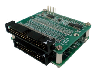
DIO-8/4RE-UBCとAIO-32/0RA-IRC をスタックして取り付けます。
-
DIO-8/4RE-UBCをパソコンとUSBケーブルで接続します。
電源が供給されますので、金属などの導電性のある物とボードが触れないように注意してください。
-
プログラムを実行します。
アナログ入力電圧が表示されます。
CH0: 5.205V
CH1: 0.000V
CH2: 0.000V
...
使用方法について
差動入力で使用する場合
analog_read_volt関数 または analog_read関数 で引数(channel)を以下の値にすることで、各差動入力チャネルの電圧を読み出すことが可能です。
channelの値 = 差動入力チャネル * 17 + 256
| channel | 差動入力チャネル | 接続先 |
|---|---|---|
| 256 | 差動入力チャネル0 | P1-1pinとP1-2pin |
| 273 | 差動入力チャネル1 | P1-3pinとP1-4pin |
| 290 | 差動入力チャネル2 | P1-5pinとP1-6pin |
| ・・・ |
必ず入力信号の基準電位(0V)を、AG(P1-33pin・P1-34pinどちらかのピン)に接続してください。